
- Assigning of electrical installation characteristics,
- Assigning of Technological characteristics,
- Using Architecture assessment criteria,
- Step (1): Choice of distribution architecture fundamentals,
- Step (2): choice of architecture details,
- Step (3): choice of equipment,
- Recommendations for architecture optimization.
And I explained the first four tasks in the following previous topics:
- The Electrical Distribution Architecture – Part Seven
- The Electrical Distribution Architecture – Part Eight
Today, I will explain the fifth task; Step (2): choice of architecture details as follows.
Fifth: Step (2): choice of architecture details
As I mentioned before in the previous topic " The Electrical Distribution Architecture – Part Eight " that the single-line diagram can be broken down into different key parts, which are determined throughout a process in 2 successive steps, which are:
- Step (1): Choice of distribution architecture fundamentals,
- Step (2): choice of architecture details.
During Step (1): Choice of distribution architecture fundamentals, as explained in the past Topic above, we made the following choices:
- Connection to the utilities network,
- Configuration of MV circuits,
- Number and distribution of transformation substations,
- Number of power transformers,
- MV back-up generator.
While during Step (2): choice of architecture details, we will make the following choices:
- Layout,
- Centralized or decentralized distribution,
- Presence of LV back-up generators,
- Presence of uninterruptible power supplies,
- Configuration of LV circuits,
1- Layout
Layout means the Position of the main MV and LV equipment on the site or in the building. This layout choice is applied to the results of stage 1.
Selection guide:
- Place power sources as close as possible to the barycenter of power consumers,
- Reduce atmospheric constraints: building dedicated premises if the layout in the workshop is too restrictive (temperature, vibrations, dusts, etc.),
- Placing heavy equipment (transformers, generators, etc) close to walls or main exists for ease of maintenance,
 |
| Fig (1): Layout |
A layout example is given in the following Fig (1), where the barycenter of the electrical loads on this site was represented by the hatched circle and all the power sources and power distribution placed near to this barycenter.
2- Centralized or decentralized distribution
The location of the consumers with respect to the power sources and the consumer distribution along the layout result in two modes of Electrical Distribution Architecture as follows (see fig.2):
- Centralized layout,
- Decentralized layout.
 |
| Fig (2): Centralized or decentralized distribution |
a- Centralized layout
In centralized layout, current consumers are connected to the power sources by a star-connection. Cables are suitable for centralized layout, with point to point links between the MLVS and current consumers or sub-distribution boards (radial distribution, star- distribution) (Fig.2)
Advantages:
- Power supply by cables gives greater independence of circuits (lighting, power sockets, HVAC, motors, auxiliaries, security, etc), reducing the consequences of a fault from the point of view of power availability.
Factors in favour of centralized layout (see summary table#1 in below):
- Installation flexibility: no,
- Load distribution: localized loads (high unit power loads).
b- Decentralized layout
In decentralized layout, current consumers are connected to sources via a busway. Busbar trunking systems are well suited to decentralized layout, to supply many loads that are spread out, making it easy to change, move or add connections (Fig.2):
Advantages:
- The use of busbar trunking systems allows load power circuits to be combined and saves on conductors by taking advantage of a clustering coefficient. The choice between cable and busbar trunking, according to the clustering coefficient, allows us to find an economic optimum between investment costs, implementation costs and operating costs.
Factors in favor of decentralized layout:
- Installation flexibility: "Implementation" flexibility (moving of workstations, etc…),
- Load distribution: uniform distribution of low unit power loads
The following table summarizes Method of Loads distribution and the effect of Installation Flexibility level on the Configuration of Electrical Distribution Architecture:
|
Installation Flexibility Level
|
Loads Distribution
|
||
|
Localized Loads
|
Intermediate Distribution
|
Uniform Distributed
|
|
|
No
Flexibility
|
Layout#1
Centralized
|
Layout#1
Centralized
|
Layout#2
Decentralized
|
|
Design Flexibility
|
|||
|
Implementation
Flexibility
|
Layout#2
Decentralized
|
||
|
Operation Flexibility
|
|||
Where:
- Localized Loads: localized in certain, fixed and separated positions.
- Intermediate distribution: Localized in certain positions but distributed along the floor.
- Uniform distributed: loads spread out along the floor.
Notes:
- The Centralized and Decentralized distribution modes are often combined.
3- Presence of LV back-up generators (fig.3)
 |
| Fig (3) |
- Sensitivity of loads to power interruption,
- Availability of the public distribution network,
a- Sensitivity of loads to power interruption
This is expressed in terms of the criticality of supplying of loads or circuits as follows:
- Non-Critical: The load or the circuit can be “shed” at any time and it doesn’t need a back-up generators. E.g.: sanitary water heating circuit.
- Low Criticality: A power interruption causes temporary discomfort for the occupants of a building, without any financial consequences. Prolonging of the interruption beyond the critical time can cause a loss of production or lower productivity and it usually doesn’t need a back-up generators. E.g.: heating, ventilation and air conditioning circuits (HVAC).
- Medium Criticality: A power interruption causes a short break in process or service. Prolonging of the interruption beyond a critical time can cause a deterioration of the production facilities or a cost of starting for starting back up and it usually needs a back-up generators. E.g.: refrigerated units, lifts.
- High Criticality: Any power interruption causes mortal danger or unacceptable financial losses and a back-up generator is a must. E.g.: operating theatre, IT department, security department.
b- Availability of the public distribution network
Please review the previous topic " The Electrical Distribution Architecture – Part Seven".
Notes:
- According to the generator’s capacity to supply power to all or only part of the installation, there is either total or partial redundancy.
- A back-up generator functions generally disconnected from the network. A source switching system is therefore necessary.
- The generator can function permanently or intermittently. Its back-up time depends on the quantity of available fuel.
- Determining the number of back-up generator units is in line with the same criteria as determining the number of transformers, as well as taking account of economic and availability considerations (redundancy, start-up reliability, maintenance facility).
- Generators are compulsory in hospitals or high-vise buildings.
- The electrical power supply supplied by a back-up generator is produced by an alternator, driven by a thermal engine. So, No power can be produced until the generator has reached its rated speed. A back-up generator is therefore not suitable for an uninterrupted power supply.
4- Presence of uninterruptible power supplies (UPS)
- The electrical power from a UPS is supplied from a storage unit: batteries or inertia wheel with a limited backup time range from several minutes to several hours.
- The presence of a UPS unit is essential if and only if no power failure is acceptable.
- A UPS unit is also used for supply power to loads that are sensitive to disturbances (generating a “clean” voltage that is independent of the network).
a- Sensitivity of loads to power interruptions,
This characteristic explained above.
b- Sensitivity of loads to disturbances.
Please review the previous topic " The Electrical Distribution Architecture – Part Four ".
Simultaneous presence of a back-up generator and a UPS
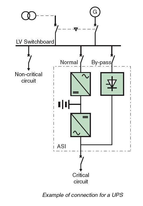 |
| Fig (4) |
- The simultaneous presence of a back-up generator and a UPS unit is used for permanently supply loads for which no failure is acceptable (Fig.4).
- The back-up time of the battery or the inertia wheel must be compatible with the maximum time for the generator to start up and be brought on-line.
5- Configuration of LV circuits
Main possible configurations (see Fig.5) are:
a- Radial single feeder configuration
This is the reference configuration and the most simple. A load is connected to only one single source. This configuration provides a minimum level of availability, since there is no redundancy in case of power source failure.
b- Two-pole configuration
The power supply is provided by 2 transformers, connected to the same MV line. When the transformers are close, they are generally connected in parallel to the same MLVS.
c- Variant: two-pole with two ½ MLVS
In order to increase the availability in case of failure of the busbars or authorize maintenance on one of the transformers, it is possible to split the MLVS into 2 parts, with a normally open link (NO). This configuration generally requires an Automatic Transfer Switch, (ATS).
d- Shedable switchboard (simple disconnectable attachment)
A series of shedable circuits can be connected to a dedicated switchboard. The connection to the MLVS is interrupted when needed (overload, generator operation, etc)
e- Interconnected switchboards
If transformers are physically distant from one another, they may be connected by a busbar trunking. A critical load can be supplied by one or other of the transformers. The availability of power is therefore improved, since the load can always be supplied in the case of failure of one of the sources.
The redundancy can be:
f- Ring configuration
This configuration can be considered as an extension of the configuration with interconnection between switchboards. Typically, 4 transformers connected to the same MV line, supply a ring using busbar trunking. A given load is then supplied power by several clustered transformers. This configuration is well suited to extended installations, with a high load density (in kVA/m²). If all of the loads can be supplied by 3 transformers, there is total redundancy in the case of failure of one of the transformers. In fact, each busbar can be fed power by one or other of its ends. Otherwise, downgraded operation must be considered (with partial load shedding). This configuration requires special design of the protection plan in order to ensure discrimination in all of the fault circumstances.
g- Double-ended power supply
This configuration is implemented in cases where maximum availability is required. The principle involves having 2 independent power sources, e.g.:
An automatic transfer switch (ATS) is used to avoid the sources being parallel connected. This configuration allows preventive and curative maintenance to be carried out on all of the electrical distribution system upstream without interrupting the power supply.
The following table summarizes the different possible Configurations of Electrical Distribution Architecture (LV Part) with the usual set of Characteristics:
Configuration combinations (fig.6)
- Radial single feeder configuration
- Two-pole configuration
- Variant: two-pole with two ½ MLVS
- Shedable switchboard
- Interconnected switchboards
- Ring configuration
- Double-ended power supply
| Fig (5): Configuration of LV circuits |
a- Radial single feeder configuration
This is the reference configuration and the most simple. A load is connected to only one single source. This configuration provides a minimum level of availability, since there is no redundancy in case of power source failure.
b- Two-pole configuration
The power supply is provided by 2 transformers, connected to the same MV line. When the transformers are close, they are generally connected in parallel to the same MLVS.
c- Variant: two-pole with two ½ MLVS
In order to increase the availability in case of failure of the busbars or authorize maintenance on one of the transformers, it is possible to split the MLVS into 2 parts, with a normally open link (NO). This configuration generally requires an Automatic Transfer Switch, (ATS).
d- Shedable switchboard (simple disconnectable attachment)
A series of shedable circuits can be connected to a dedicated switchboard. The connection to the MLVS is interrupted when needed (overload, generator operation, etc)
e- Interconnected switchboards
If transformers are physically distant from one another, they may be connected by a busbar trunking. A critical load can be supplied by one or other of the transformers. The availability of power is therefore improved, since the load can always be supplied in the case of failure of one of the sources.
The redundancy can be:
- Total: each transformer being capable of supplying all of the installation,
- Partial: each transformer only being able to supply part of the installation. In this case, part of the loads must be disconnected (load-shedding) in the case of one of the transformers failing.
f- Ring configuration
This configuration can be considered as an extension of the configuration with interconnection between switchboards. Typically, 4 transformers connected to the same MV line, supply a ring using busbar trunking. A given load is then supplied power by several clustered transformers. This configuration is well suited to extended installations, with a high load density (in kVA/m²). If all of the loads can be supplied by 3 transformers, there is total redundancy in the case of failure of one of the transformers. In fact, each busbar can be fed power by one or other of its ends. Otherwise, downgraded operation must be considered (with partial load shedding). This configuration requires special design of the protection plan in order to ensure discrimination in all of the fault circumstances.
g- Double-ended power supply
This configuration is implemented in cases where maximum availability is required. The principle involves having 2 independent power sources, e.g.:
- (2) transformers supplied by different MV lines,
- (1) transformer and (1) generator,
- (1) transformer and (1) UPS.
An automatic transfer switch (ATS) is used to avoid the sources being parallel connected. This configuration allows preventive and curative maintenance to be carried out on all of the electrical distribution system upstream without interrupting the power supply.
The following table summarizes the different possible Configurations of Electrical Distribution Architecture (LV Part) with the usual set of Characteristics:
|
Characteristic To Be Considered
|
Configuration Of LV Circuits
|
|||||
|
Radial
|
Two-Pole
|
Sheddable
Load
|
Interconnected
Switchboard
|
Ring
|
Double-Ended
|
|
|
Site topology
|
Any
|
Any
|
Any
|
1 level 5 to 25000m²
|
1 level 5 to 25000m²
|
Any
|
|
Location latitude
|
Any
|
Any
|
Any
|
Medium or high
|
Medium or high
|
Any
|
|
Maintainability
|
Minimal
|
Standard
|
Minimal
|
Standard
|
Standard
|
Enhanced
|
|
Power demand
|
< 2500kVA
|
Any
|
Any
|
≥ 1250kVA
|
> 2500kVA
|
Any
|
|
Load distribution
|
Localized loads
|
Localized loads
|
Localized load
|
Intermediate or uniform distribution
|
Uniform distribution
|
Localized loads
|
|
Interruptions sensitivity
|
Long interruption acceptable
|
Long interruption acceptable
|
Sheddable
|
Long interruption acceptable
|
Long interruption acceptable
|
Short or no interruption
|
|
Disturbances sensitivity
|
Low sensitivity
|
High sensitivity
|
Low sensitivity
|
High sensitivity
|
High sensitivity
|
High sensitivity
|
|
Other constraints
|
/
|
/
|
/
|
/
|
/
|
Double-ended loads
|
Configuration combinations (fig.6)
 |
| Fig (6) |
An installation can be made up of several sub-assemblies with different configurations, according to requirements for the availability of the different types of load. E.g.: generator unit and UPS, choice by sectors (some sectors supplied by cables and others by busbar trunking).
In the next topic, I will explain Step (3): choice of equipment and Recommendations for architecture optimization. So, please keep following.

No comments:
Post a Comment