
In the In the previous article “Calculux Software for Lighting Design – Part Four “. I explained Example for lighting design calculations by using Calculux Indoor Software.
Today I will continue explaining the same example#2 from the previous article as follows.
You can review the following prevoius articles about CalcuLux software for more information and good following:
Step#7: Defining Switching Modes
The following four switching modes will be defined for this project:
- General lighting;
- Task lighting for bureau;
- Task lighting for table;
- Accent lighting for painting at right wall.
A- Defining the name of the switching modes
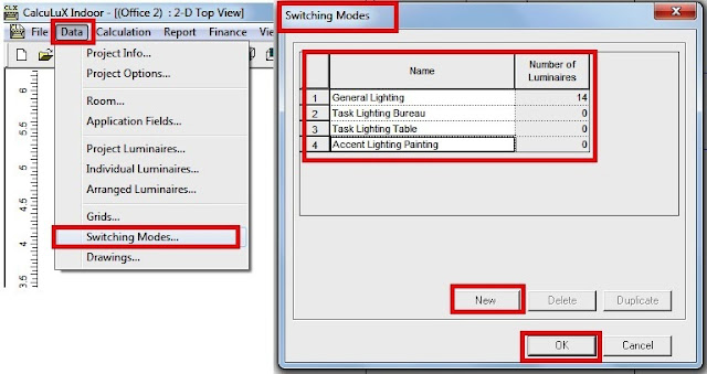
- Select Switching Modes from the Data menu.
- In the Switching Modes dialogue box, enter the names of the switching modes as follows:
- Enter General Lighting, then click New.
- Enter Task Lighting Bureau, then click New.
- Enter Task Lighting Table, then click New.
- Enter Accent Lighting Painting, then click OK.
Note:
In this example project the General Lighting is always switched on.
B- Selecting the luminaires to which the switching mode is applied
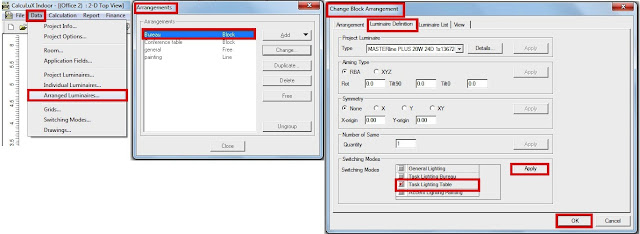
- Select Arranged Luminaires from the Data menu.
- Select the Luminaire Definition tab.
- In the Switching Modes box, check 'Task Lighting Bureau' only.
- Click Apply, then OK.
2-Double click on 'Conference Table' in the Arrangements dialogue box.

- Select the Luminaire Definition tab.
- In the Switching Modes box, check 'Task Lighting Table' only.
- Click Apply, then OK.
3-Double click on 'Painting' in the Arrangements dialogue box.

- Select the Luminaire Definition tab.
- In the Switching Modes box, check 'Accent Lighting Painting' only.
- Click Apply, then OK.
4-Double click on 'General' in the Arrangements dialogue box.
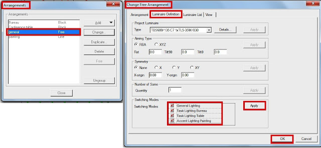
- Select the Luminaire Definition tab.
- In the Switching Modes box, check 'General Lighting', 'Task Lighting Bureau', 'Task Lighting Table' and 'Accent Lighting Painting'.
- Click Apply, then OK.
- Click Close.
Step#8: Defining Calculations
Before you can perform a calculation, you have to specify the calculation name and the calculation parameters first.
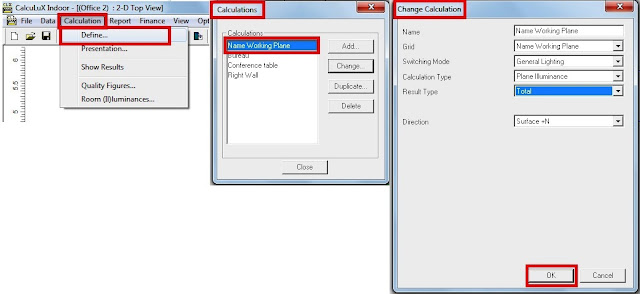
- Select Define from the Calculation menu.
- For this project the following calculations have to be defined:
1- Working Plane
a-Double click on 'Working Plane' in the Calculation dialogue box.
b-In the Change Calculation dialogue box, check and/or select:
- Name: Working Plane
- Grid : Working Plane
- Switching Mode: General Lighting
- Calculation Type: Plane Illuminance
- Result Type: Total (= Direct + Indirect contribution)
- Direction Surface: +N
c-Click OK.
2- Bureau

a-Double click on 'Bureau' in the Calculation dialogue box.
b-In the Change Calculation dialogue box, check and/or select:
- Name: Bureau
- Grid: Bureau
- Switching Mode: Task Lighting Bureau
- Calculation Type: Plane Illuminance
- Result Type: Total (= Direct + Indirect contribution)
- Direction Surface: +N
c-Click OK.
3- Conference table

a-Double click on 'Conference table' in the Calculation dialogue box.
b-In the Change Calculation dialogue box, check and/or select:
- Name: Conference Table
- Grid: Conference Table
- Switching Mode: Task Lighting Table
- Calculation Type: Plane Illuminance
- Result Type: Total (= Direct + Indirect contribution)
- Direction Surface: +N
c-Click OK.
4- Right Wall

a-Double click on 'Right Wall' in the Calculation dialogue box.
b-In the Change Calculation dialogue box, check and/or select:
c-Click OK, then Close.
Step#9: Defining the Calculation Presentation
1- Set the options for calculation presentation of Bureau:
2- Set the options for calculation presentation of Conference table:
Step#10: Creating a report
1- Enter new Project Information
b-In the Change Calculation dialogue box, check and/or select:
- Name: Right Wall
- Grid: Right Wall
- Switching Mode Accent Lighting Painting
- Calculation Type: Plane Illuminance
- Result Type: Total (= Direct + Indirect contribution)
- Direction Surface: +N
c-Click OK, then Close.
Step#9: Defining the Calculation Presentation
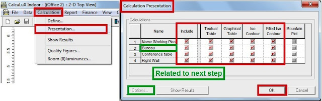
- Select Presentation from the Calculation menu.
- In the Include box, double click on the + or - sign to include (+) or exclude (-) a calculation. For this project Working Plane, Bureau, Conference table and Right Wall have to be included.
- In the Presentation Forms box, select in which presentation forms the calculation results of Working Plane, Bureau, Conference table and Right Wall are presented. Select:
- Textual Table;
- Filled Iso Contour.
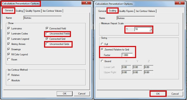
1- Set the options for calculation presentation of Bureau:
- In the Calculation Presentation dialogue box, select Bureau, Click Options.
- Select the General tab.
- In the Show box, set which attributes are shown in the calculation presentation, Disable (no cross):
- Unconnected Field
- Unconnected Grid
- Select the Scaling tab.
- In the Minimum Report Scale box, select the scaling of the report, select: 1: 10
- In the Sizing box, select:
- Zoomed Relative to Grid
- Factor 1.000
- Click OK.
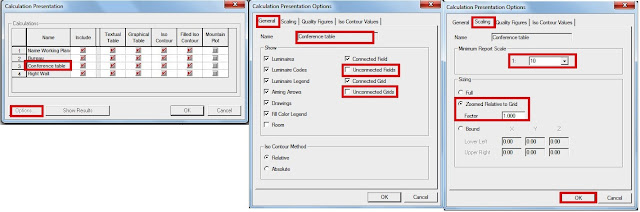
2- Set the options for calculation presentation of Conference table:
- In the Calculation Presentation dialogue box, select Conference table, Click Options.
- Select the General tab.
- In the Show box, set which attributes are shown in the calculation presentation, Disable (no cross):
- Unconnected Field
- Unconnected Grid
- Select the Scaling tab.
- In the Minimum Report Scale box, select the scaling of the report, select: 1: 10
- In the Sizing box, select:
- Zoomed Relative to Grid
- Factor 1.000
- Click OK.
- Click OK to return to the Main View.
Step#10: Creating a report
1- Enter new Project Information
Before you create a report you should enter information about the project. This information will be printed on the title page of your report.
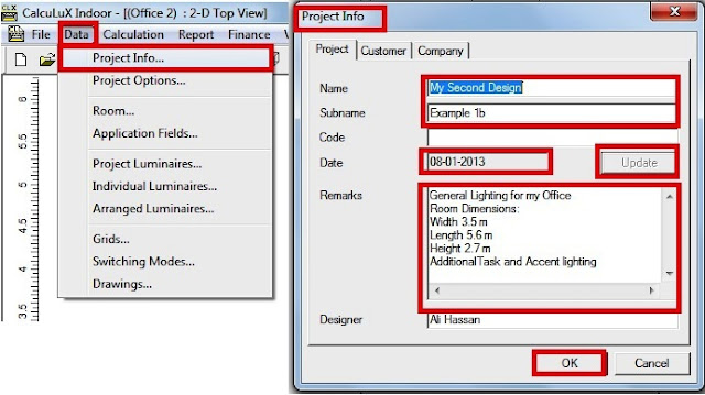
- Select Project Info from the Data menu.
- In the Project tab you can enter project information as in the following table:
|
Name:
|
My Second
Design
|
|
Subname:
|
Example 1b
|
|
Remarks:
|
General
Lighting for my Office
Room
Dimensions:
Width 3.5 m
Length 5.6 m
Height 2.7 m
Additional
Task- and Accent Lighting.
|
- Click OK.
Note: For this project the Grid points and Luminaire Code have not to be displayed.
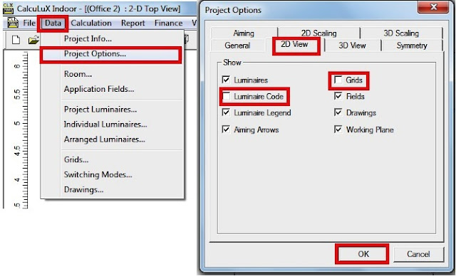
- Select Project Options from the Data menu.
- Select the 2D View tab.
- In the Show box, Luminaire Code and Grids should not be checked (no cross).
- Click OK.
3- Report Setup

- Select Setup from the Report menu.
- Select the Components tab.
- In the Components box, select which components have to be included in the report. Include:
- Title Page
- Table of Contents
- Top Project Overview
- Summary
- Luminaire Details
- Installation Data
- In the Include box, double click on the + or - sign to include (+) or exclude (-) a calculation.
Note: For this project Working Plane, Bureau, Table and Right Wall have to be included.
- In the Presentation Forms box, select in which presentation forms the calculation results are presented. Select:
- Graphical Table
- Iso Contour
- Filled Iso Contour
- Click OK.
Step#11: Printing the Report
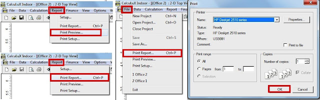
Note: You can use Print Preview (see Report menu) to preview your report before printing it.
- Select Print Report from the File menu or Report menu.
- Click OK in the Print dialogue box to print the report.
Step#12: Saving the project
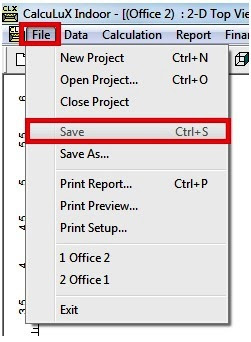
Note: In case you wish to redesign the project later, it is advisable to save the project.
- Select Save from the File menu to save the project.
The final report for this example#2 will be like the following image:

You can download the final report for this example by clicking the link.
In the next article, I will explain additional tasks (Indirect, Curtain, Painting and Whiteboard) that can be done in lighting design calculation by using CalcuLux Indoor Software. Please, keep following.

No comments:
Post a Comment